Tutorial
Physical Layer
Data Link layer
Network Layer
Routing Algorithm
Transport Layer
Application Layer
Network Security
Misc
- Router
- OSI vs TCP/IP
- TCP vs UDP
- Transmission Control Protocol
- TCP port
- IPv4 vs IPv6
- ARP Packet Format
- ARP Table
- Working of ARP
- FTP Client
- FTP Commands
- FTP Server
- I2C Protocol
- Sliding Window Protocol
- SPI Protocol
- IP
- ARP Commands
- ARP
- Address Resolution Protocol
- ARP and its types
- TCP Retransmission
- CAN protocol
- HTTP Status Codes
- HTTP vs HTTPS
- RIP Protocol
- UDP Protocol
- ICMP Protocol
- MQTT protocol
- OSPF Protocol
- Stop and Wait Protocol
- IMAP Protocol
- POP Protocol
- CIFS
- DAS
- DIMM
- iSCSI
- NAS (Network Attached Storage)
- NFS
- NVMe
- SAN
- Border Gateway Protocol
- Go-Back-N ARQ
- RJ Cable
- Difference between Connection-Oriented and Connectionless Service
- CDMA vs. GSM
- What is MAC Address
- Modem vs. Router
- Switch Vs. Router
- USB 2.0 vs 3.0
- Difference between CSMA CA and CSMA CD
- Multiple access protocol- ALOHA, CSMA, CSMA/CA and CSMA/CD
- URI vs URL
- IMAP vs. POP3
- SSH Meaning| SSH Protocol
- UTP vs STP
- Status Code 400
- MIME Protocol
- IP address
- proxy server
- How to set up and use a proxy server
- network security
- WWW is based on which model
- Proxy Server List
- Fundamentals of Computer Networking
- IP Address Format and Table
- Bus topology and Ring topology
- Bus topology and Star topology
- Circuit Switching and Packet switching?
- Difference between star and ring topology
- Difference between Router and Bridge
- TCP Connection Termination
- Image Steganography
- Network Neutrality
- Onion Routing
- Adaptive security appliance (ASA) features
- Relabel-to-front Algorithm
- Types of Server Virtualization in Computer Network
- Access Lists (ACL)
- What is a proxy server and how does it work
- Digital Subscriber Line (DSL)
- Operating system based Virtualization
- Context based Access Control (CBAC)
- Cristian's Algorithm
- Service Set Identifier (SSID)
- Voice over Internet Protocol (VoIP)
- Challenge Response Authentication Mechanism (CRAM)
- Extended Access List
- Li-fi vs. Wi-fi
- Reflexive Access List
- Synchronous Optical Network (SONET)
- Wifi protected access (WPA)
- Wifi Protected Setup (WPS)
- Standard Access List
- Time Access List
- What is 3D Internet
- 4G Mobile Communication Technology
- Types of Wireless Transmission Media
- Best Computer Networking Courses
- Data Representation
- Network Criteria
- Classful vs Classless addressing
- Difference between BOOTP and RARP in Computer Networking
- What is AGP (Accelerated Graphics Port)
- Advantages and Disadvantages of Satellite Communication
- External IP Address
- Asynchronous Transfer Mode (ATM)
- Types of Authentication Protocols
- What is a CISCO Packet Tracer
- BOOTP work
- Subnetting in Computer Networks
- Mesh Topology Advantages and Disadvantages
- Ring Topology Advantages and Disadvantages
- Star Topology Advantages and Disadvantages
- Tree Topology Advantages and Disadvantages
- Zigbee Technology-The smart home protocol
- Network Layer in OSI Model
- Physical Layer in OSI Model
- Data Link Layer in OSI Model
- Internet explorer shortcut keys
- Network Layer Security | SSL Protocols
- Presentation Layer in OSI Model
- Session Layer in OSI Model
- SUBNET MASK
- Transport Layer Security | Secure Socket Layer (SSL) and SSL Architecture
- Functions, Advantages and Disadvantages of Network Layer
- Protocols in Noiseless and Noisy Channel
- Advantages and Disadvantages of Mesh Topology
- Cloud Networking - Managing and Optimizing Cloud-Based Networks
- Collision Domain and Broadcast Domain
- Count to Infinity Problem in Distance Vector Routing
- Difference Between Go-Back-N and Selective Repeat Protocol
- Difference between Stop and Wait, GoBackN, and Selective Repeat
- Network Function Virtualization (NFV): transforming Network Architecture with Virtualized Functions
- Network-Layer Security | IPSec Modes
- Next - Prev Network-Layer Security | IPSec Protocols and Services
- Ping vs Traceroute
- Software Defined Networking (SDN): Benefits and Challenges of Network Virtualization
- Software Defined Networking (SDN) vs. Network Function Virtualization (NFV)
- Virtual Circuits vs Datagram Networks
- BlueSmack Attack in Wireless Networks
- Bluesnarfing Attack in Wireless Networks
- Direct Sequence Spread Spectrum
- Warchalking in Wireless Networks
- WEP (Wired Equivalent Privacy)
- Wireless security encryption
- Wireless Security in an Enterprise
- Quantum Networking
- Network Automation
- Difference between MSS and MTU
- What is MTU
- Mesh Networks: A decentralized and Self-Organizing Approach to Networking
- What is Autonomous System
- What is MSS
- Cyber security & Software security
- Information security & Network security.
- Security Engineer & Security Architect
- Protection Methods for Network Security
- Trusted Systems in Network Security
- What are Authentication Tokens in Network security
- Cookies in Network Security
- Intruders in Network Security
- Network Security Toolkit (NST) in virtual box
- Pivoting-Moving Inside a Network
- Security Environment in Computer Networks
- Voice Biometric technique in Network Security
- Advantages and Disadvantages of Conventional Testing
- Difference between Kerberos and LDAP
- Cyber security and Information Security
- GraphQL Attacks and Security
- Application Layer in OSI Model
- Applications of Remote Sensing
- Seven Layers of IT Security
- What is Ad Hoc TCP
- What is Server Name Indication(SNI)
Multiplexing
Multiplexing is a technique used to combine and send the multiple data streams over a single medium. The process of combining the data streams is known as multiplexing and hardware used for multiplexing is known as a multiplexer.
Multiplexing is achieved by using a device called Multiplexer (MUX) that combines n input lines to generate a single output line. Multiplexing follows many-to-one, i.e., n input lines and one output line.
Demultiplexing is achieved by using a device called Demultiplexer (DEMUX) available at the receiving end. DEMUX separates a signal into its component signals (one input and n outputs). Therefore, we can say that demultiplexing follows the one-to-many approach.
Why Multiplexing?
- The transmission medium is used to send the signal from sender to receiver. The medium can only have one signal at a time.
- If there are multiple signals to share one medium, then the medium must be divided in such a way that each signal is given some portion of the available bandwidth. For example: If there are 10 signals and bandwidth of medium is100 units, then the 10 unit is shared by each signal.
- When multiple signals share the common medium, there is a possibility of collision. Multiplexing concept is used to avoid such collision.
- Transmission services are very expensive.
History of Multiplexing
- Multiplexing technique is widely used in telecommunications in which several telephone calls are carried through a single wire.
- Multiplexing originated in telegraphy in the early 1870s and is now widely used in communication.
- George Owen Squier developed the telephone carrier multiplexing in 1910.
Concept of Multiplexing

- The 'n' input lines are transmitted through a multiplexer and multiplexer combines the signals to form a composite signal.
- The composite signal is passed through a Demultiplexer and demultiplexer separates a signal to component signals and transfers them to their respective destinations.
Advantages of Multiplexing:
- More than one signal can be sent over a single medium.
- The bandwidth of a medium can be utilized effectively.
Multiplexing Techniques
Multiplexing techniques can be classified as:
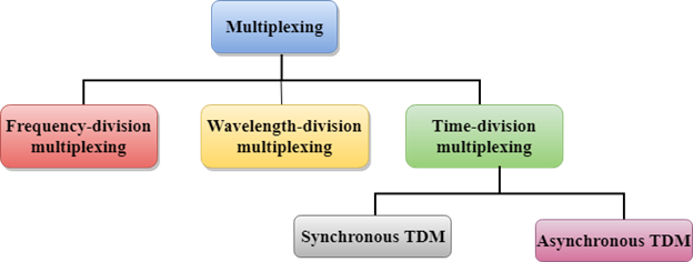
Frequency-division Multiplexing (FDM)
- It is an analog technique.
- Frequency Division Multiplexing is a technique in which the available bandwidth of a single transmission medium is subdivided into several channels.
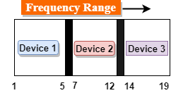
- In the above diagram, a single transmission medium is subdivided into several frequency channels, and each frequency channel is given to different devices. Device 1 has a frequency channel of range from 1 to 5.
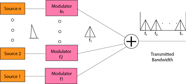
- The input signals are translated into frequency bands by using modulation techniques, and they are combined by a multiplexer to form a composite signal.
- The main aim of the FDM is to subdivide the available bandwidth into different frequency channels and allocate them to different devices.
- Using the modulation technique, the input signals are transmitted into frequency bands and then combined to form a composite signal.
- The carriers which are used for modulating the signals are known as sub-carriers. They are represented as f1,f2..fn.
- FDM is mainly used in radio broadcasts and TV networks.
Advantages Of FDM:
- FDM is used for analog signals.
- FDM process is very simple and easy modulation.
- A Large number of signals can be sent through an FDM simultaneously.
- It does not require any synchronization between sender and receiver.
Disadvantages Of FDM:
- FDM technique is used only when low-speed channels are required.
- It suffers the problem of crosstalk.
- A Large number of modulators are required.
- It requires a high bandwidth channel.
Applications Of FDM:
- FDM is commonly used in TV networks.
- It is used in FM and AM broadcasting. Each FM radio station has different frequencies, and they are multiplexed to form a composite signal. The multiplexed signal is transmitted in the air.
Wavelength Division Multiplexing (WDM)
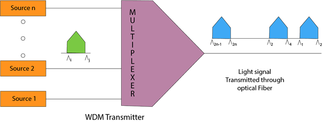
- Wavelength Division Multiplexing is same as FDM except that the optical signals are transmitted through the fibre optic cable.
- WDM is used on fibre optics to increase the capacity of a single fibre.
- It is used to utilize the high data rate capability of fibre optic cable.
- It is an analog multiplexing technique.
- Optical signals from different source are combined to form a wider band of light with the help of multiplexer.
- At the receiving end, demultiplexer separates the signals to transmit them to their respective destinations.
- Multiplexing and Demultiplexing can be achieved by using a prism.
- Prism can perform a role of multiplexer by combining the various optical signals to form a composite signal, and the composite signal is transmitted through a fibre optical cable.
- Prism also performs a reverse operation, i.e., demultiplexing the signal.

Time Division Multiplexing
- It is a digital technique.
- In Frequency Division Multiplexing Technique, all signals operate at the same time with different frequency, but in case of Time Division Multiplexing technique, all signals operate at the same frequency with different time.
- In Time Division Multiplexing technique, the total time available in the channel is distributed among different users. Therefore, each user is allocated with different time interval known as a Time slot at which data is to be transmitted by the sender.
- A user takes control of the channel for a fixed amount of time.
- In Time Division Multiplexing technique, data is not transmitted simultaneously rather the data is transmitted one-by-one.
- In TDM, the signal is transmitted in the form of frames. Frames contain a cycle of time slots in which each frame contains one or more slots dedicated to each user.
- It can be used to multiplex both digital and analog signals but mainly used to multiplex digital signals.
There are two types of TDM:
- Synchronous TDM
- Asynchronous TDM
Synchronous TDM
- A Synchronous TDM is a technique in which time slot is preassigned to every device.
- In Synchronous TDM, each device is given some time slot irrespective of the fact that the device contains the data or not.
- If the device does not have any data, then the slot will remain empty.
- In Synchronous TDM, signals are sent in the form of frames. Time slots are organized in the form of frames. If a device does not have data for a particular time slot, then the empty slot will be transmitted.
- The most popular Synchronous TDM are T-1 multiplexing, ISDN multiplexing, and SONET multiplexing.
- If there are n devices, then there are n slots.
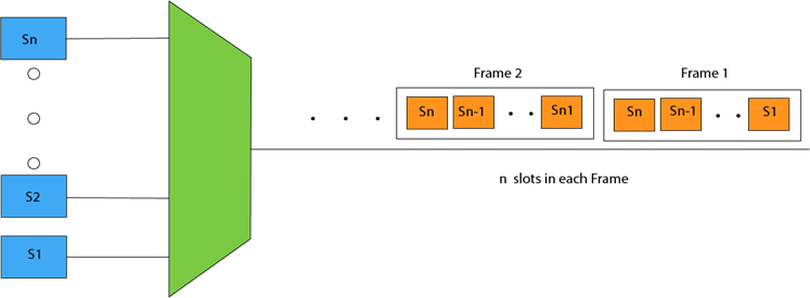
Concept Of Synchronous TDM
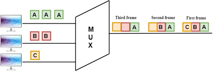
In the above figure, the Synchronous TDM technique is implemented. Each device is allocated with some time slot. The time slots are transmitted irrespective of whether the sender has data to send or not.
Disadvantages Of Synchronous TDM:
- The capacity of the channel is not fully utilized as the empty slots are also transmitted which is having no data. In the above figure, the first frame is completely filled, but in the last two frames, some slots are empty. Therefore, we can say that the capacity of the channel is not utilized efficiently.
- The speed of the transmission medium should be greater than the total speed of the input lines. An alternative approach to the Synchronous TDM is Asynchronous Time Division Multiplexing.
Asynchronous TDM
- An asynchronous TDM is also known as Statistical TDM.
- An asynchronous TDM is a technique in which time slots are not fixed as in the case of Synchronous TDM. Time slots are allocated to only those devices which have the data to send. Therefore, we can say that Asynchronous Time Division multiplexor transmits only the data from active workstations.
- An asynchronous TDM technique dynamically allocates the time slots to the devices.
- In Asynchronous TDM, total speed of the input lines can be greater than the capacity of the channel.
- Asynchronous Time Division multiplexor accepts the incoming data streams and creates a frame that contains only data with no empty slots.
- In Asynchronous TDM, each slot contains an address part that identifies the source of the data.

- The difference between Asynchronous TDM and Synchronous TDM is that many slots in Synchronous TDM are unutilized, but in Asynchronous TDM, slots are fully utilized. This leads to the smaller transmission time and efficient utilization of the capacity of the channel.
- In Synchronous TDM, if there are n sending devices, then there are n time slots. In Asynchronous TDM, if there are n sending devices, then there are m time slots where m is less than n (m<n).
- The number of slots in a frame depends on the statistical analysis of the number of input lines.
Concept Of Asynchronous TDM
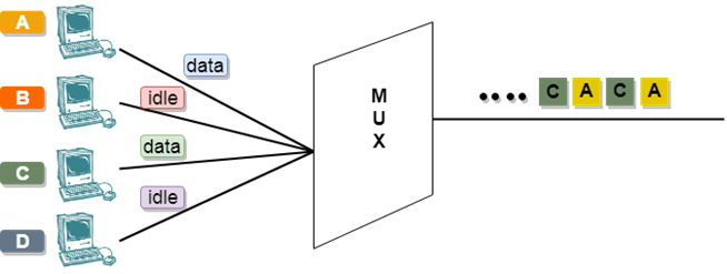
In the above diagram, there are 4 devices, but only two devices are sending the data, i.e., A and C. Therefore, the data of A and C are only transmitted through the transmission line.
Frame of above diagram can be represented as:
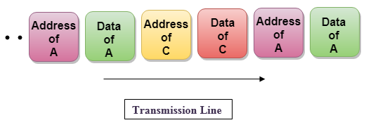
The above figure shows that the data part contains the address to determine the source of the data.


