Tutorial
Physical Layer
Data Link layer
Network Layer
Routing Algorithm
Transport Layer
Application Layer
Network Security
Misc
- Router
- OSI vs TCP/IP
- TCP vs UDP
- Transmission Control Protocol
- TCP port
- IPv4 vs IPv6
- ARP Packet Format
- ARP Table
- Working of ARP
- FTP Client
- FTP Commands
- FTP Server
- I2C Protocol
- Sliding Window Protocol
- SPI Protocol
- IP
- ARP Commands
- ARP
- Address Resolution Protocol
- ARP and its types
- TCP Retransmission
- CAN protocol
- HTTP Status Codes
- HTTP vs HTTPS
- RIP Protocol
- UDP Protocol
- ICMP Protocol
- MQTT protocol
- OSPF Protocol
- Stop and Wait Protocol
- IMAP Protocol
- POP Protocol
- CIFS
- DAS
- DIMM
- iSCSI
- NAS (Network Attached Storage)
- NFS
- NVMe
- SAN
- Border Gateway Protocol
- Go-Back-N ARQ
- RJ Cable
- Difference between Connection-Oriented and Connectionless Service
- CDMA vs. GSM
- What is MAC Address
- Modem vs. Router
- Switch Vs. Router
- USB 2.0 vs 3.0
- Difference between CSMA CA and CSMA CD
- Multiple access protocol- ALOHA, CSMA, CSMA/CA and CSMA/CD
- URI vs URL
- IMAP vs. POP3
- SSH Meaning| SSH Protocol
- UTP vs STP
- Status Code 400
- MIME Protocol
- IP address
- proxy server
- How to set up and use a proxy server
- network security
- WWW is based on which model
- Proxy Server List
- Fundamentals of Computer Networking
- IP Address Format and Table
- Bus topology and Ring topology
- Bus topology and Star topology
- Circuit Switching and Packet switching?
- Difference between star and ring topology
- Difference between Router and Bridge
- TCP Connection Termination
- Image Steganography
- Network Neutrality
- Onion Routing
- Adaptive security appliance (ASA) features
- Relabel-to-front Algorithm
- Types of Server Virtualization in Computer Network
- Access Lists (ACL)
- What is a proxy server and how does it work
- Digital Subscriber Line (DSL)
- Operating system based Virtualization
- Context based Access Control (CBAC)
- Cristian's Algorithm
- Service Set Identifier (SSID)
- Voice over Internet Protocol (VoIP)
- Challenge Response Authentication Mechanism (CRAM)
- Extended Access List
- Li-fi vs. Wi-fi
- Reflexive Access List
- Synchronous Optical Network (SONET)
- Wifi protected access (WPA)
- Wifi Protected Setup (WPS)
- Standard Access List
- Time Access List
- What is 3D Internet
- 4G Mobile Communication Technology
- Types of Wireless Transmission Media
- Best Computer Networking Courses
- Data Representation
- Network Criteria
- Classful vs Classless addressing
- Difference between BOOTP and RARP in Computer Networking
- What is AGP (Accelerated Graphics Port)
- Advantages and Disadvantages of Satellite Communication
- External IP Address
- Asynchronous Transfer Mode (ATM)
- Types of Authentication Protocols
- What is a CISCO Packet Tracer
- BOOTP work
- Subnetting in Computer Networks
- Mesh Topology Advantages and Disadvantages
- Ring Topology Advantages and Disadvantages
- Star Topology Advantages and Disadvantages
- Tree Topology Advantages and Disadvantages
- Zigbee Technology-The smart home protocol
- Network Layer in OSI Model
- Physical Layer in OSI Model
- Data Link Layer in OSI Model
- Internet explorer shortcut keys
- Network Layer Security | SSL Protocols
- Presentation Layer in OSI Model
- Session Layer in OSI Model
- SUBNET MASK
- Transport Layer Security | Secure Socket Layer (SSL) and SSL Architecture
- Functions, Advantages and Disadvantages of Network Layer
- Protocols in Noiseless and Noisy Channel
- Advantages and Disadvantages of Mesh Topology
- Cloud Networking - Managing and Optimizing Cloud-Based Networks
- Collision Domain and Broadcast Domain
- Count to Infinity Problem in Distance Vector Routing
- Difference Between Go-Back-N and Selective Repeat Protocol
- Difference between Stop and Wait, GoBackN, and Selective Repeat
- Network Function Virtualization (NFV): transforming Network Architecture with Virtualized Functions
- Network-Layer Security | IPSec Modes
- Next - Prev Network-Layer Security | IPSec Protocols and Services
- Ping vs Traceroute
- Software Defined Networking (SDN): Benefits and Challenges of Network Virtualization
- Software Defined Networking (SDN) vs. Network Function Virtualization (NFV)
- Virtual Circuits vs Datagram Networks
- BlueSmack Attack in Wireless Networks
- Bluesnarfing Attack in Wireless Networks
- Direct Sequence Spread Spectrum
- Warchalking in Wireless Networks
- WEP (Wired Equivalent Privacy)
- Wireless security encryption
- Wireless Security in an Enterprise
- Quantum Networking
- Network Automation
- Difference between MSS and MTU
- What is MTU
- Mesh Networks: A decentralized and Self-Organizing Approach to Networking
- What is Autonomous System
- What is MSS
- Cyber security & Software security
- Information security & Network security.
- Security Engineer & Security Architect
- Protection Methods for Network Security
- Trusted Systems in Network Security
- What are Authentication Tokens in Network security
- Cookies in Network Security
- Intruders in Network Security
- Network Security Toolkit (NST) in virtual box
- Pivoting-Moving Inside a Network
- Security Environment in Computer Networks
- Voice Biometric technique in Network Security
- Advantages and Disadvantages of Conventional Testing
- Difference between Kerberos and LDAP
- Cyber security and Information Security
- GraphQL Attacks and Security
- Application Layer in OSI Model
- Applications of Remote Sensing
- Seven Layers of IT Security
- What is Ad Hoc TCP
- What is Server Name Indication(SNI)
Error Correction
Error Correction codes are used to detect and correct the errors when data is transmitted from the sender to the receiver.
Error Correction can be handled in two ways:
- Backward error correction: Once the error is discovered, the receiver requests the sender to retransmit the entire data unit.
- Forward error correction: In this case, the receiver uses the error-correcting code which automatically corrects the errors.
A single additional bit can detect the error, but cannot correct it.
For correcting the errors, one has to know the exact position of the error. For example, If we want to calculate a single-bit error, the error correction code will determine which one of seven bits is in error. To achieve this, we have to add some additional redundant bits.
Suppose r is the number of redundant bits and d is the total number of the data bits. The number of redundant bits r can be calculated by using the formula:
2r>=d+r+1
The value of r is calculated by using the above formula. For example, if the value of d is 4, then the possible smallest value that satisfies the above relation would be 3.
To determine the position of the bit which is in error, a technique developed by R.W Hamming is Hamming code which can be applied to any length of the data unit and uses the relationship between data units and redundant units.
Hamming Code
Parity bits: The bit which is appended to the original data of binary bits so that the total number of 1s is even or odd.
Even parity: To check for even parity, if the total number of 1s is even, then the value of the parity bit is 0. If the total number of 1s occurrences is odd, then the value of the parity bit is 1.
Odd Parity: To check for odd parity, if the total number of 1s is even, then the value of parity bit is 1. If the total number of 1s is odd, then the value of parity bit is 0.
Algorithm of Hamming code:
- An information of 'd' bits are added to the redundant bits 'r' to form d+r.
- The location of each of the (d+r) digits is assigned a decimal value.
- The 'r' bits are placed in the positions 1,2,.....2k-1.
- At the receiving end, the parity bits are recalculated. The decimal value of the parity bits determines the position of an error.
Relationship b/w Error position & binary number.
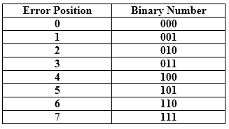
Let's understand the concept of Hamming code through an example:
Suppose the original data is 1010 which is to be sent.
Total number of data bits 'd' = 4
Number of redundant bits r : 2r >= d+r+1
                           2r>= 4+r+1
Therefore, the value of r is 3 that satisfies the above relation.
Total number of bits = d+r = 4+3 = 7;
Determining the position of the redundant bits
The number of redundant bits is 3. The three bits are represented by r1, r2, r4. The position of the redundant bits is calculated with corresponds to the raised power of 2. Therefore, their corresponding positions are 1, 21, 22.
- The position of r1 = 1
- The position of r2 = 2
- The position of r4 = 4
Representation of Data on the addition of parity bits:

Determining the Parity bits
Determining the r1 bit
The r1 bit is calculated by performing a parity check on the bit positions whose binary representation includes 1 in the first position.
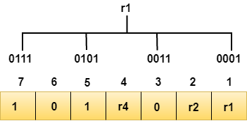
We observe from the above figure that the bit positions that includes 1 in the first position are 1, 3, 5, 7. Now, we perform the even-parity check at these bit positions. The total number of 1 at these bit positions corresponding to r1 is even, therefore, the value of the r1 bit is 0.
Determining r2 bit
The r2 bit is calculated by performing a parity check on the bit positions whose binary representation includes 1 in the second position.
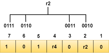
We observe from the above figure that the bit positions that includes 1 in the second position are 2, 3, 6, 7. Now, we perform the even-parity check at these bit positions. The total number of 1 at these bit positions corresponding to r2 is odd, therefore, the value of the r2 bit is 1.
Determining r4 bit
The r4 bit is calculated by performing a parity check on the bit positions whose binary representation includes 1 in the third position.
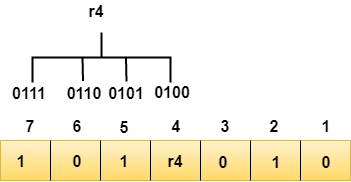
We observe from the above figure that the bit positions that includes 1 in the third position are 4, 5, 6, 7. Now, we perform the even-parity check at these bit positions. The total number of 1 at these bit positions corresponding to r4 is even, therefore, the value of the r4 bit is 0.
Data transferred is given below:

Suppose the 4th bit is changed from 0 to 1 at the receiving end, then parity bits are recalculated.
R1 bit
The bit positions of the r1 bit are 1,3,5,7
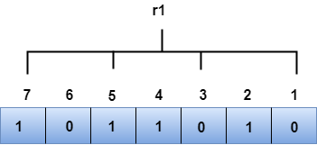
We observe from the above figure that the binary representation of r1 is 1100. Now, we perform the even-parity check, the total number of 1s appearing in the r1 bit is an even number. Therefore, the value of r1 is 0.
R2 bit
The bit positions of r2 bit are 2,3,6,7.
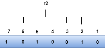
We observe from the above figure that the binary representation of r2 is 1001. Now, we perform the even-parity check, the total number of 1s appearing in the r2 bit is an even number. Therefore, the value of r2 is 0.
R4 bit
The bit positions of r4 bit are 4,5,6,7.
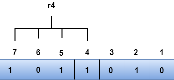
We observe from the above figure that the binary representation of r4 is 1011. Now, we perform the even-parity check, the total number of 1s appearing in the r4 bit is an odd number. Therefore, the value of r4 is 1.
- The binary representation of redundant bits, i.e., r4r2r1 is 100, and its corresponding decimal value is 4. Therefore, the error occurs in a 4th bit position. The bit value must be changed from 1 to 0 to correct the error.


