Tutorial
Physical Layer
Data Link layer
Network Layer
Routing Algorithm
Transport Layer
Application Layer
Network Security
Misc
- Router
- OSI vs TCP/IP
- TCP vs UDP
- Transmission Control Protocol
- TCP port
- IPv4 vs IPv6
- ARP Packet Format
- ARP Table
- Working of ARP
- FTP Client
- FTP Commands
- FTP Server
- I2C Protocol
- Sliding Window Protocol
- SPI Protocol
- IP
- ARP Commands
- ARP
- Address Resolution Protocol
- ARP and its types
- TCP Retransmission
- CAN protocol
- HTTP Status Codes
- HTTP vs HTTPS
- RIP Protocol
- UDP Protocol
- ICMP Protocol
- MQTT protocol
- OSPF Protocol
- Stop and Wait Protocol
- IMAP Protocol
- POP Protocol
- CIFS
- DAS
- DIMM
- iSCSI
- NAS (Network Attached Storage)
- NFS
- NVMe
- SAN
- Border Gateway Protocol
- Go-Back-N ARQ
- RJ Cable
- Difference between Connection-Oriented and Connectionless Service
- CDMA vs. GSM
- What is MAC Address
- Modem vs. Router
- Switch Vs. Router
- USB 2.0 vs 3.0
- Difference between CSMA CA and CSMA CD
- Multiple access protocol- ALOHA, CSMA, CSMA/CA and CSMA/CD
- URI vs URL
- IMAP vs. POP3
- SSH Meaning| SSH Protocol
- UTP vs STP
- Status Code 400
- MIME Protocol
- IP address
- proxy server
- How to set up and use a proxy server
- network security
- WWW is based on which model
- Proxy Server List
- Fundamentals of Computer Networking
- IP Address Format and Table
- Bus topology and Ring topology
- Bus topology and Star topology
- Circuit Switching and Packet switching?
- Difference between star and ring topology
- Difference between Router and Bridge
- TCP Connection Termination
- Image Steganography
- Network Neutrality
- Onion Routing
- Adaptive security appliance (ASA) features
- Relabel-to-front Algorithm
- Types of Server Virtualization in Computer Network
- Access Lists (ACL)
- What is a proxy server and how does it work
- Digital Subscriber Line (DSL)
- Operating system based Virtualization
- Context based Access Control (CBAC)
- Cristian's Algorithm
- Service Set Identifier (SSID)
- Voice over Internet Protocol (VoIP)
- Challenge Response Authentication Mechanism (CRAM)
- Extended Access List
- Li-fi vs. Wi-fi
- Reflexive Access List
- Synchronous Optical Network (SONET)
- Wifi protected access (WPA)
- Wifi Protected Setup (WPS)
- Standard Access List
- Time Access List
- What is 3D Internet
- 4G Mobile Communication Technology
- Types of Wireless Transmission Media
- Best Computer Networking Courses
- Data Representation
- Network Criteria
- Classful vs Classless addressing
- Difference between BOOTP and RARP in Computer Networking
- What is AGP (Accelerated Graphics Port)
- Advantages and Disadvantages of Satellite Communication
- External IP Address
- Asynchronous Transfer Mode (ATM)
- Types of Authentication Protocols
- What is a CISCO Packet Tracer
- BOOTP work
- Subnetting in Computer Networks
- Mesh Topology Advantages and Disadvantages
- Ring Topology Advantages and Disadvantages
- Star Topology Advantages and Disadvantages
- Tree Topology Advantages and Disadvantages
- Zigbee Technology-The smart home protocol
- Network Layer in OSI Model
- Physical Layer in OSI Model
- Data Link Layer in OSI Model
- Internet explorer shortcut keys
- Network Layer Security | SSL Protocols
- Presentation Layer in OSI Model
- Session Layer in OSI Model
- SUBNET MASK
- Transport Layer Security | Secure Socket Layer (SSL) and SSL Architecture
- Functions, Advantages and Disadvantages of Network Layer
- Protocols in Noiseless and Noisy Channel
- Advantages and Disadvantages of Mesh Topology
- Cloud Networking - Managing and Optimizing Cloud-Based Networks
- Collision Domain and Broadcast Domain
- Count to Infinity Problem in Distance Vector Routing
- Difference Between Go-Back-N and Selective Repeat Protocol
- Difference between Stop and Wait, GoBackN, and Selective Repeat
- Network Function Virtualization (NFV): transforming Network Architecture with Virtualized Functions
- Network-Layer Security | IPSec Modes
- Next - Prev Network-Layer Security | IPSec Protocols and Services
- Ping vs Traceroute
- Software Defined Networking (SDN): Benefits and Challenges of Network Virtualization
- Software Defined Networking (SDN) vs. Network Function Virtualization (NFV)
- Virtual Circuits vs Datagram Networks
- BlueSmack Attack in Wireless Networks
- Bluesnarfing Attack in Wireless Networks
- Direct Sequence Spread Spectrum
- Warchalking in Wireless Networks
- WEP (Wired Equivalent Privacy)
- Wireless security encryption
- Wireless Security in an Enterprise
- Quantum Networking
- Network Automation
- Difference between MSS and MTU
- What is MTU
- Mesh Networks: A decentralized and Self-Organizing Approach to Networking
- What is Autonomous System
- What is MSS
- Cyber security & Software security
- Information security & Network security.
- Security Engineer & Security Architect
- Protection Methods for Network Security
- Trusted Systems in Network Security
- What are Authentication Tokens in Network security
- Cookies in Network Security
- Intruders in Network Security
- Network Security Toolkit (NST) in virtual box
- Pivoting-Moving Inside a Network
- Security Environment in Computer Networks
- Voice Biometric technique in Network Security
- Advantages and Disadvantages of Conventional Testing
- Difference between Kerberos and LDAP
- Cyber security and Information Security
- GraphQL Attacks and Security
- Application Layer in OSI Model
- Applications of Remote Sensing
- Seven Layers of IT Security
- What is Ad Hoc TCP
- What is Server Name Indication(SNI)
CAN protocol
CAN stands for Controller Area Network protocol. It is a protocol that was developed by Robert Bosch in around 1986. The CAN protocol is a standard designed to allow the microcontroller and other devices to communicate with each other without any host computer. The feature that makes the CAN protocol unique among other communication protocols is the broadcast type of bus. Here, broadcast means that the information is transmitted to all the nodes. The node can be a sensor, microcontroller, or a gateway that allows the computer to communicate over the network through the USB cable or ethernet port. The CAN is a message-based protocol, which means that message carries the message identifier, and based on the identifier, priority is decided. There is no need for node identification in the CAN network, so it becomes very easy to insert or delete it from the network. It is a serial half-duplex and asynchronous type of communication protocol. The CAN is a two-wired communication protocol as the CAN network is connected through the two-wired bus. The wires are twisted pair having 120Ω characteristics impedance connected at each end. Initially, it was mainly designed for communication within the vehicles, but it is now used in many other contexts. Like UDS, and KWP 2000, CAN also be used for the on-board diagnostics.
Why CAN?
The need for a centralized standard communication protocol came because of the increase in the number of electronic devices. For example, there can be more than 7 TCU for various subsystems such as dashboard, transmission control, engine control unit, and many more in a modern vehicle. If all the nodes are connected one-to-one, then the speed of the communication would be very high, but the complexity and cost of the wires would be very high. In the above example, a single dashboard requires 8 connectors, so to overcome this issue, CAN was introduced as a centralized solution that requires two wires, i.e., CAN high and CAN low. The solution of using CAN protocol is quite efficient due to its message prioritization, and flexible as a node can be inserted or removed without affecting the network.
Applications of CAN protocol
Initially, CAN protocol was designed to target the communication issue that occurs within the vehicles. But later on, due to the features it offers, it is used in various other fields. The following are the applications of CAN protocol:
- Automotive (passenger vehicles, trucks, buses)
- Electronic equipment for aviation and navigation
- Industrial automation and mechanical control
- Elevator and escalators
- Building automation
- Medical instruments and equipment
- Marine, medical, industrial, medical
CAN layered architecture
As we know that the OSI model partitions the communication system into 7 different layers. But the CAN layered architecture consists of two layers, i.e., data-link layer and physical layer.
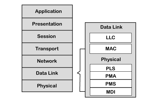
Let's understand both the layers.
- Data-link layer: This layer is responsible for node to node data transfer. It allows you to establish and terminate the connection. It is also responsible for detecting and correcting the errors that may occur at the physical layer. Data-link layer is subdivided into two sub-layers:
- MAC: MAC stands for Media Access Control. It defines how devices in a network gain access to the medium. It provides Encapsulation and Decapsulation of data, Error detection, and signaling.
- LLC: LLC stands for Logical link control. It is responsible for frame acceptance filtering, overload notification, and recovery management.
- Physical layer: The physical layer is responsible for the transmission of raw data. It defines the specifications for the parameters such as voltage level, timing, data rates, and connector.
CAN specifications define CAN protocol and CAN physical layer, which are defined in the CAN standard ISO 11898. ISO 11898 has three parts:
- ISO 11898-1: This part contains the specification of the Data-link layer and physical signal link.
- ISO 11898-2: This part comes under CAN physical layer for high speed CAN. The high- speed CAN allows data rate upto 1 Mbps used in the power train and the charges area of the vehicle.
- ISO 11898-3: This part also comes under CAN physical layer for low-speed CAN. It allows data rate upto 125 kbps, and the low speed CAN is used where the speed of communication is not a critical factor.
CiA DS-102: The full form of CiA is CAN in Automation, which defines the specifications for the CAN connector.
As far as the implementation is concerned, the CAN controller and CAN transceiver are implemented in the software with the help of the application, operating system, and network management functions.
CAN Framing
Let's understand the structure of the CAN frame.

- SOF: SOF stands for the start of frame, which indicates that the new frame is entered in a network. It is of 1 bit.
- Identifier: A standard data format defined under the CAN 2.0 A specification uses an 11-bit message identifier for arbitration. Basically, this message identifier sets the priority of the data frame.
- RTR: RTR stands for Remote Transmission Request, which defines the frame type, whether it is a data frame or a remote frame. It is of 1-bit.
- Control field: It has user-defined functions.
- IDE: An IDE bit in a control field stands for identifier extension. A dominant IDE bit defines the 11-bit standard identifier, whereas recessive IDE bit defines the 29-bit extended identifier.
- DLC: DLC stands for Data Length Code, which defines the data length in a data field. It is of 4 bits.
- Data field: The data field can contain upto 8 bytes.
- CRC field: The data frame also contains a cyclic redundancy check field of 15 bit, which is used to detect the corruption if it occurs during the transmission time. The sender will compute the CRC before sending the data frame, and the receiver also computes the CRC and then compares the computed CRC with the CRC received from the sender. If the CRC does not match, then the receiver will generate the error.
- ACK field: This is the receiver's acknowledgment. In other protocols, a separate packet for an acknowledgment is sent after receiving all the packets, but in case of CAN protocol, no separate packet is sent for an acknowledgment.
- EOF: EOF stands for end of frame. It contains 7 consecutive recessive bits known End of frame.
Now we will see how data is transmitted through the CAN network.
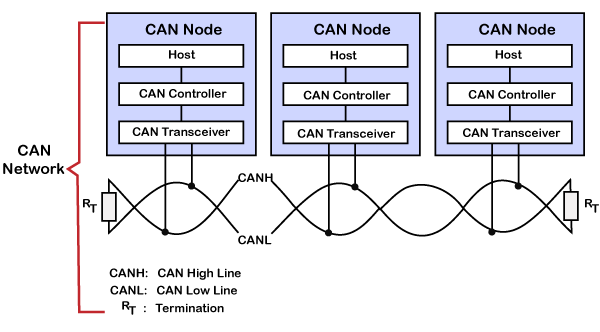
A CAN network consists of multiple of CAN nodes. In the above case, we have considered three CAN nodes, and named them as node A, node B, and node C. CAN node consists of three elements which are given below:
- Host
A host is a microcontroller or microprocessor which is running some application to do a specific job. A host decides what the received message means and what message it should send next. - CAN Controller
CAN controller deals with the communication functions described by the CAN protocol. It also triggers the transmission, or the reception of the CAN messages. - CAN Transceiver
CAN transceiver is responsible for the transmission or the reception of the data on the CAN bus. It converts the data signal into the stream of data collected from the CAN bus that the CAN controller can understand.
In the above diagram, unshielded twisted pair cable is used to transmit or receive the data. It is also known as CAN bus, and CAN bus consists of two lines, i.e., CAN low line and CAN high line, which are also known as CANH and CANL, respectively. The transmission occurs due to the differential voltage applied to these lines. The CAN uses twisted pair cable and differential voltage because of its environment. For example, in a car, motor, ignition system, and many other devices can cause data loss and data corruption due to noise. The twisting of the two lines also reduces the magnetic field. The bus is terminated with 120Ω resistance at each end.
CAN Characteristics
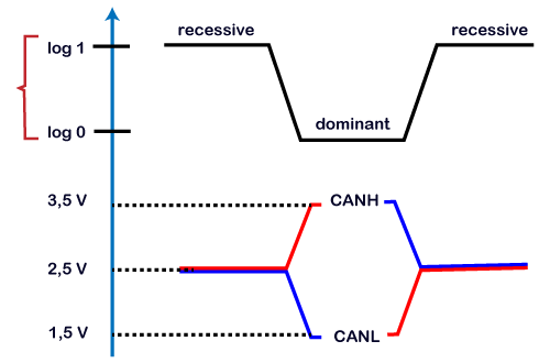
With the help of differential voltage, we will determine how 0 and 1 are transmitted through the CAN bus. The above figure is the voltage graph that shows the voltage level of CAN low and CAN high. In CAN terminology, logic 1 is said to be recessive while logic 0 is dominant. When CAN high line and CAN low line are applied with 2.5 volts, then the actual differential voltage would be zero volt. A zero volt on CAN bus is read by the CAN transceiver as a recessive or logic 1. A zero volt on CAN bus is an ideal state of the bus. When CAN high line is pulled up to 3.5 volt and the CAN low line is pulled down to 1.5 volt, then the bus's actual differential voltage would be 2 volts. It is treated as a dominant bit or logic 0 by the CAN transceiver. If the bus state is reached to dominant or logic 0 then it would become impossible to move to the recessive state by any other node.
Key points learnt from the CAN characteristics
- Logic 1 is a recessive state. To transmit 1 on CAN bus, both CAN high and CAN low should be applied with 2.5V.
- Logic 0 is a dominant state. To transmit 0 on CAN bus, CAN high should be applied at 3.5V and CAN low should be applied at 1.5V.
- The ideal state of the bus is recessive.
- If the node reaches the dominant state, it cannot move back to the recessive state by any other node.
CAN bus logic
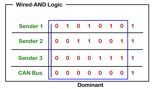
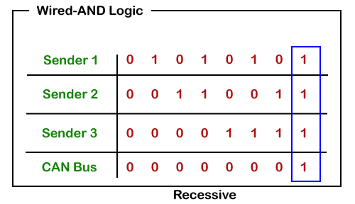
From the above scenario, we get to know that the dominant state overwrites the recessive state. When the node sends the dominant and the recessive bit simultaneously, then the bus remains dominant. The recessive level occurs only when all the nodes send the recessive bit. Such logic is known as AND logic, and physically it is implemented as an open collector circuit.
CAN Communication Principle
As we know that the message is sent based on the priority set in the arbitration field. For the standard frame, the message identifier is 11 bit, while for the extended frame, the message identifier is 29 bit. It allows the system designer to design the message identifier at the design itself. The smaller the message identifier, the higher, would be the message priority.
Let's understand how arbitration works through a flow chart.
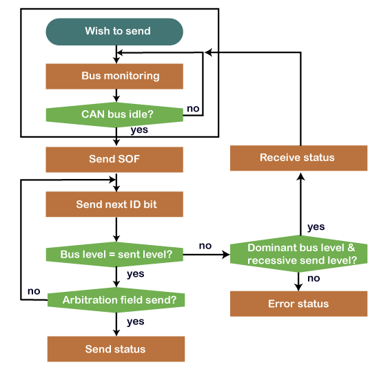
The sender wants to send the message and waiting for the CAN bus to become idle. If the CAN bus is idle, then the sender sends the SOF or the dominant bit for the bus access. Then, it sends the message identifier bit in the most significant bit. If the node detects the dominant bit on the bus while it has transmitted the recessive bit, it means that the node has lost the arbitration and stops transmitting further bits. The sender will wait and resend the message once the bus is free.
CAN Arbitration Example
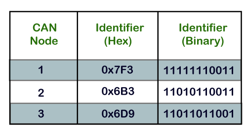
If we consider three nodes, i.e., Node 1, Node 2, and Node 3, the message identifiers of these nodes are 0x7F3, 0x6B3, and 0x6D9, respectively.
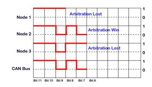
The transmission of all the three nodes with the most significant bit is shown in the above diagram.
11th bit: As all the three bits of nodes are recessive, so bus bit will also remain recessive.
10th bit: All the nodes have 10th bit as recessive, so the bus will also remain recessive.
9th bit: Node 1 has recessive bit while other nodes have a dominant bit, so the bus will also remain dominant. In this case, node 1 has lost the arbitration, so it stops sending bits.
8th bit: Both node 2 and node 3 are sending recessive bit, so that the bus state will remain recessive.
7th bit: The node 2 is sending dominant bit while node 3 has sent recessive bit, so that the bus state will remain dominant. In this case, the node 3 has lost the arbitration, so it stops sending the message while the node 2 has won the arbitration means that it will continue to hold the bus until the message is received.


