Tutorial
Physical Layer
Data Link layer
Network Layer
Routing Algorithm
Transport Layer
Application Layer
Network Security
Misc
- Router
- OSI vs TCP/IP
- TCP vs UDP
- Transmission Control Protocol
- TCP port
- IPv4 vs IPv6
- ARP Packet Format
- ARP Table
- Working of ARP
- FTP Client
- FTP Commands
- FTP Server
- I2C Protocol
- Sliding Window Protocol
- SPI Protocol
- IP
- ARP Commands
- ARP
- Address Resolution Protocol
- ARP and its types
- TCP Retransmission
- CAN protocol
- HTTP Status Codes
- HTTP vs HTTPS
- RIP Protocol
- UDP Protocol
- ICMP Protocol
- MQTT protocol
- OSPF Protocol
- Stop and Wait Protocol
- IMAP Protocol
- POP Protocol
- CIFS
- DAS
- DIMM
- iSCSI
- NAS (Network Attached Storage)
- NFS
- NVMe
- SAN
- Border Gateway Protocol
- Go-Back-N ARQ
- RJ Cable
- Difference between Connection-Oriented and Connectionless Service
- CDMA vs. GSM
- What is MAC Address
- Modem vs. Router
- Switch Vs. Router
- USB 2.0 vs 3.0
- Difference between CSMA CA and CSMA CD
- Multiple access protocol- ALOHA, CSMA, CSMA/CA and CSMA/CD
- URI vs URL
- IMAP vs. POP3
- SSH Meaning| SSH Protocol
- UTP vs STP
- Status Code 400
- MIME Protocol
- IP address
- proxy server
- How to set up and use a proxy server
- network security
- WWW is based on which model
- Proxy Server List
- Fundamentals of Computer Networking
- IP Address Format and Table
- Bus topology and Ring topology
- Bus topology and Star topology
- Circuit Switching and Packet switching?
- Difference between star and ring topology
- Difference between Router and Bridge
- TCP Connection Termination
- Image Steganography
- Network Neutrality
- Onion Routing
- Adaptive security appliance (ASA) features
- Relabel-to-front Algorithm
- Types of Server Virtualization in Computer Network
- Access Lists (ACL)
- What is a proxy server and how does it work
- Digital Subscriber Line (DSL)
- Operating system based Virtualization
- Context based Access Control (CBAC)
- Cristian's Algorithm
- Service Set Identifier (SSID)
- Voice over Internet Protocol (VoIP)
- Challenge Response Authentication Mechanism (CRAM)
- Extended Access List
- Li-fi vs. Wi-fi
- Reflexive Access List
- Synchronous Optical Network (SONET)
- Wifi protected access (WPA)
- Wifi Protected Setup (WPS)
- Standard Access List
- Time Access List
- What is 3D Internet
- 4G Mobile Communication Technology
- Types of Wireless Transmission Media
- Best Computer Networking Courses
- Data Representation
- Network Criteria
- Classful vs Classless addressing
- Difference between BOOTP and RARP in Computer Networking
- What is AGP (Accelerated Graphics Port)
- Advantages and Disadvantages of Satellite Communication
- External IP Address
- Asynchronous Transfer Mode (ATM)
- Types of Authentication Protocols
- What is a CISCO Packet Tracer
- BOOTP work
- Subnetting in Computer Networks
- Mesh Topology Advantages and Disadvantages
- Ring Topology Advantages and Disadvantages
- Star Topology Advantages and Disadvantages
- Tree Topology Advantages and Disadvantages
- Zigbee Technology-The smart home protocol
- Network Layer in OSI Model
- Physical Layer in OSI Model
- Data Link Layer in OSI Model
- Internet explorer shortcut keys
- Network Layer Security | SSL Protocols
- Presentation Layer in OSI Model
- Session Layer in OSI Model
- SUBNET MASK
- Transport Layer Security | Secure Socket Layer (SSL) and SSL Architecture
- Functions, Advantages and Disadvantages of Network Layer
- Protocols in Noiseless and Noisy Channel
- Advantages and Disadvantages of Mesh Topology
- Cloud Networking - Managing and Optimizing Cloud-Based Networks
- Collision Domain and Broadcast Domain
- Count to Infinity Problem in Distance Vector Routing
- Difference Between Go-Back-N and Selective Repeat Protocol
- Difference between Stop and Wait, GoBackN, and Selective Repeat
- Network Function Virtualization (NFV): transforming Network Architecture with Virtualized Functions
- Network-Layer Security | IPSec Modes
- Next - Prev Network-Layer Security | IPSec Protocols and Services
- Ping vs Traceroute
- Software Defined Networking (SDN): Benefits and Challenges of Network Virtualization
- Software Defined Networking (SDN) vs. Network Function Virtualization (NFV)
- Virtual Circuits vs Datagram Networks
- BlueSmack Attack in Wireless Networks
- Bluesnarfing Attack in Wireless Networks
- Direct Sequence Spread Spectrum
- Warchalking in Wireless Networks
- WEP (Wired Equivalent Privacy)
- Wireless security encryption
- Wireless Security in an Enterprise
- Quantum Networking
- Network Automation
- Difference between MSS and MTU
- What is MTU
- Mesh Networks: A decentralized and Self-Organizing Approach to Networking
- What is Autonomous System
- What is MSS
- Cyber security & Software security
- Information security & Network security.
- Security Engineer & Security Architect
- Protection Methods for Network Security
- Trusted Systems in Network Security
- What are Authentication Tokens in Network security
- Cookies in Network Security
- Intruders in Network Security
- Network Security Toolkit (NST) in virtual box
- Pivoting-Moving Inside a Network
- Security Environment in Computer Networks
- Voice Biometric technique in Network Security
- Advantages and Disadvantages of Conventional Testing
- Difference between Kerberos and LDAP
- Cyber security and Information Security
- GraphQL Attacks and Security
- Application Layer in OSI Model
- Applications of Remote Sensing
- Seven Layers of IT Security
- What is Ad Hoc TCP
- What is Server Name Indication(SNI)
ICMP Protocol
The ICMP stands for Internet Control Message Protocol. It is a network layer protocol. It is used for error handling in the network layer, and it is primarily used on network devices such as routers. As different types of errors can exist in the network layer, so ICMP can be used to report these errors and to debug those errors.
For example, some sender wants to send the message to some destination, but the router couldn't send the message to the destination. In this case, the router sends the message to the sender that I could not send the message to that destination.
The IP protocol does not have any error-reporting or error-correcting mechanism, so it uses a message to convey the information. For example, if someone sends the message to the destination, the message is somehow stolen between the sender and the destination. If no one reports the error, then the sender might think that the message has reached the destination. If someone in-between reports the error, then the sender will resend the message very quickly.
Position of ICMP in the network layer
The ICMP resides in the IP layer, as shown in the below diagram.

Messages
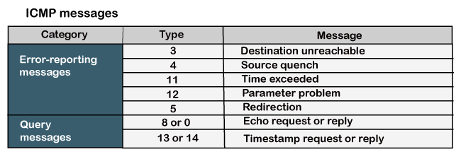
The ICMP messages are usually divided into two categories:

- Error-reporting messages
The error-reporting message means that the router encounters a problem when it processes an IP packet then it reports a message.
- Query messages
The query messages are those messages that help the host to get the specific information of another host. For example, suppose there are a client and a server, and the client wants to know whether the server is live or not, then it sends the ICMP message to the server.
ICMP Message Format
The message format has two things; one is a category that tells us which type of message it is. If the message is of error type, the error message contains the type and the code. The type defines the type of message while the code defines the subtype of the message.
The ICMP message contains the following fields:

- Type: It is an 8-bit field. It defines the ICMP message type. The values range from 0 to 127 are defined for ICMPv6, and the values from 128 to 255 are the informational messages.
- Code: It is an 8-bit field that defines the subtype of the ICMP message
- Checksum: It is a 16-bit field to detect whether the error exists in the message or not.
Note: The ICMP protocol always reports the error messages to the original source. For example, when the sender sends the message, if any error occurs in the message then the router reports to the sender rather than the receiver as the sender is sending the message.
Types of Error Reporting messages
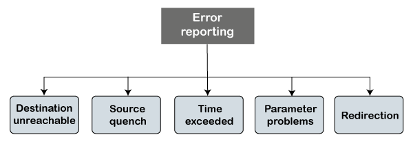
The error reporting messages are broadly classified into the following categories:

- Destination unreachable
The destination unreachable error occurs when the packet does not reach the destination. Suppose the sender sends the message, but the message does not reach the destination, then the intermediate router reports to the sender that the destination is unreachable.

The above diagram shows the message format of the destination unreachable message. In the message format:
Type: It defines the type of message. The number 3 specifies that the destination is unreachable.
Code (0 to 15): It is a 4-bit number which identifies whether the message comes from some intermediate router or the destination itself.
Note: If the destination creates the destination unreachable message then the code could be either 2 or 3.
Sometimes the destination does not want to process the request, so it sends the destination unreachable message to the source. A router does not detect all the problems that prevent the delivery of a packet.
- Source quench
There is no flow control or congestion control mechanism in the network layer or the IP protocol. The sender is concerned with only sending the packets, and the sender does not think whether the receiver is ready to receive those packets or is there any congestion occurs in the network layer so that the sender can send a lesser number of packets, so there is no flow control or congestion control mechanism. In this case, ICMP provides feedback, i.e., source quench. Suppose the sender resends the packet at a higher rate, and the router is not able to handle the high data rate. To overcome such a situation, the router sends a source quench message to tell the sender to send the packet at a lower rate.

The above diagram shows the message format of the source quench message. It is a type 4 message, and code is zero.
Note: A source quench message informs the sender that the datagram has been discarded due to the congestion occurs in the network layer.
So, the sender must either stop or slow down the sending of datagrams until the congestion is reduced. The router sends one source-quench message for each datagram that is discarded due to the congestion in the network layer.
- Time exceeded
Sometimes the situation arises when there are many routers that exist between the sender and the receiver. When the sender sends the packet, then it moves in a routing loop. The time exceeded is based on the time-to-live value. When the packet traverses through the router, then each router decreases the value of TTL by one. Whenever a router decreases a datagram with a time-to-live value to zero, then the router discards a datagram and sends the time exceeded message to the original source.
Each of the MAC layers has different data units. For example, some layers can handle upto 1500 data units, and some can handle upto 300 units. When the packet is sent from a layer having 1500 units to the layer having 300 units, then the packet is divided into fragments; this process is known as fragmentation. These 1500 units are divided into 5 fragments, i.e., f1, f2, f3, f4, f5, and these fragments reach the destination in a sequence. If all the fragments are not reached to the destination in a set time, they discard all the received fragments and send a time-exceeded message to the original source.
In the case of fragmentation, the code will be different as compared to TTL. Let's observe the message format of time exceeded.

The above message format shows that the type of time-exceeded is 11, and the code can be either 0 or 1. The code 0 represents TTL, while code 1 represents fragmentation. In a time-exceeded message, the code 0 is used by the routers to show that the time-to-live value is reached to zero.
The code 1 is used by the destination to show that all the fragments do not reach within a set time.
Parameter problems
The router and the destination host can send a parameter problem message. This message conveys that some parameters are not properly set.

The above diagram shows the message format of the parameter problem. The type of message is 12, and the code can be 0 or 1.
Redirection

When the packet is sent, then the routing table is gradually augmented and updated. The tool used to achieve this is the redirection message. For example, A wants to send the packet to B, and there are two routers exist between A and B. First, A sends the data to the router 1. The router 1 sends the IP packet to router 2 and redirection message to A so that A can update its routing table.
Note: A redirection message is sent from the router to the host on the same network.
ICMP Query Messages
The ICMP Query message is used for error handling or debugging the internet. This message is commonly used to ping a message.
Echo-request and echo-reply message
A router or a host can send an echo-request message. It is used to ping a message to another host that "Are you alive". If the other host is alive, then it sends the echo-reply message. An echo-reply message is sent by the router or the host that receives an echo-request message.
Key points of Query messages
- The echo-request message and echo-reply message can be used by the network managers to check the operation of the IP protocol. Suppose two hosts, i.e., A and B, exist, and A wants to communicate with host B. The A host can communicate to host B if the link is not broken between A and B, and B is still alive.
- The echo-request message and echo-reply message check the host's reachability, and it can be done by invoking the ping command.
The message format of echo-request and echo-reply message

The above diagram shows the message format of the echo-request and echo-reply message. The type of echo-request is 8, and the request of echo-reply is 0. The code of this message is 0.
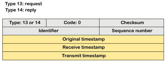
Timestamp-request and timestamp-reply message
The timestamp-request and timestamp-reply messages are also a type of query messages. Suppose the computer A wants to know the time on computer B, so it sends the timestamp-request message to computer B. The computer B responds with a timestamp-reply message.
Message format of timestamp-request and timestamp-reply

The type of timestamp-request is 13, and the type of timestamp-reply is 14. The code of this type of message is 0.
Key points related to timestamp-request and timestamp-reply message
- It can be used to calculate the round-trip time between the source and the destination, even if the clocks are not synchronized.
- It can also be used to synchronize the clocks in two different machines if the exact transit time is known.
If the sender knows the exact transit time, then it can synchronize the clock. The sender asks the time on the receiver's clock, and then it adds the time and propagation delay. Suppose the time is 1:00 clock and propagation delay is 100 ms, then time would be 1:00 clock plus 100 ms.
Debugging tools
There are several tools used for debugging. In this topic, we will learn two tools that use ICMP for debugging. The two tools are ping and traceroute. We have learned about ping in echo-request and echo-reply messages that check whether the host or a router is alive or running.
Now we will take a look at the traceroute.
Traceroute is a tool that tracks the route taken by a packet on an IP network from source to destination. It records the time taken by the packet on each hop during its route from source to destination. Traceroute uses ICMP messages and TTL values. The TTL value is calculated; if the TTL value reaches zero, the packet gets discarded. Traceroute uses small TTL values as they get quickly expired. If the TTL value is 1 then the message is produced by router 1; if the TTL value is 2 then the message is produced by router 2, and so on.
Let's understand the traceroute through an example.
Suppose A and B are two different hosts, and A wants to send the packet to the host B. Between A and B, 3 routers exist. To determine the location of the routers, we use the traceroute tool.
TTL value =1: First, host A sends the packet to router 1 with TTL value 1, and when the packet reaches to router 1 then router reduces the value of TTL by one and TTL values becomes 0. In this case, router 1 generates the time-exceeded message and host A gets to know that router 1 is the first router in a path.
TTL value=2: When host A sends the packet to router 1 with TTL value 2, and when the packet reaches to router 1 then the TTL value gets decremented by 1 and the TTL value becomes 1. Then router 1 sends the packet to router 2, and the TTL value becomes 0, so the router generates a time-exceeded message. The host A gets to know that router 2 is the second router on the path.
TTL value=3: When host A sends the packet to router 1 with TTL value 3, then the router decrements its value by one, and the TTL value becomes 2. Then, router 1 sends the packet to router 2, and the TTL value becomes 1. Then, router 2 sends the packet to router 3, and the TTL value becomes 0. As TTL value becomes 0, router 3 generates a time-exceeded message. In this way, host A is the third router on a path.


