COA Tutorial
Basic CO and Design
Computer Instructions
Digital Logic Circuits
Map Simplification
Combinational Circuits
Flip - Flops
Digital Components
Register Transfer
Micro-Operations
Memory Organization
COA_Misc
- Booth's Multiplication Algorithm
- Branch Instruction in Computer Organization
- Data Representation in Computer Organization
- ALU and Data Path in Computer Organization
- External memory in Computer Organization
- Structured Computer Organization
- Types of Register in Computer Organization
- Secondary Storage Devices in Computer Organization
- Types of Operands in Computer Organization
- Serial Communication in Computer organization
- Addressing Sequencing in Computer Organization
- Simplified Instructional Computer (SIC)
- Arithmetic Instructions in AVR microcontroller
- Conventional Computing VS Quantum Computing
- Instruction set used in Simplified Instructional Computer
- Branch Instruction in AVR microcontroller
- Conditional Branch instruction in AVR Microcontroller
- Data transfer instruction in AVR microcontroller
- Difference between Memory-based and Register-based addressing modes
- Difference between 1's complement Representation and 2's complement Representation
- CALL Instructions and Stack in AVR Microcontroller
- Difference between Call and Jump Instructions
- Overflow in Arithmetic Addition in Binary number System
- Horizontal Micro-programmed Vs. Vertical Micro-programmed Control Unit
- Hardwired Vs. Micro-programmed Control Unit
- Non-Restoring Division Algorithm for Unsigned Integer
- Restoring Division Algorithm for Unsigned Integer
- Debugging a Machine-level Program
- Dependencies and Data Hazard in pipeline in Computer Organization
- Execution, Stages and Throughput in Pipeline
- Types of Pipeline Delay and Stalling
- Timing Diagram of MOV Instruction
- Advantages and Disadvantages of Flash Memory
- Importance/Need of negative feedback in amplifiers
- Anti-Aliasing - Computer Graphics
- Bus Arbitration in Computer Organization
- Convert a number from Base 2 (Binary) to Base 6
- Cache Coherence
- EHCI
- Cache Memory and Virtual Memory
- Electrical Potential and Potential Difference
- RAM and Cache
- SIM and RIM instructions in 8085 processor
- Clusters in Computer Organization
- Data Types and Addressing Modes of 80386/80386DX Microprocessor
Register Transfer
The term Register Transfer refers to the availability of hardware logic circuits that can perform a given micro-operation and transfer the result of the operation to the same or another register.
Most of the standard notations used for specifying operations on various registers are stated below.
- The memory address register is designated by MAR.
- Program Counter PC holds the next instruction's address.
- Instruction Register IR holds the instruction being executed.
- R1 (Processor Register).
- We can also indicate individual bits by placing them in parenthesis. For instance, PC (8-15), R2 (5), etc.
- Data Transfer from one register to another register is represented in symbolic form by means of replacement operator. For instance, the following statement denotes a transfer of the data of register R1 into register R2.
- R2 ← R1
- Typically, most of the users want the transfer to occur only in a predetermined control condition. This can be shown by following if-then statement:
If (P=1) then (R2 ← R1); Here P is a control signal generated in the control section. - It is more convenient to specify a control function (P) by separating the control variables from the register transfer operation. For instance, the following statement defines the data transfer operation under a specific control function (P).
- P: R2 ← R1
The following image shows the block diagram that depicts the transfer of data from R1 to R2.
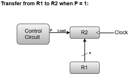
Here, the letter 'n' indicates the number of bits for the register. The 'n' outputs of the register R1 are connected to the 'n' inputs of register R2.
A load input is activated by the control variable 'P' which is transferred to the register R2.