COA Tutorial
Basic CO and Design
Computer Instructions
Digital Logic Circuits
Map Simplification
Combinational Circuits
Flip - Flops
Digital Components
Register Transfer
Micro-Operations
Memory Organization
COA_Misc
- Booth's Multiplication Algorithm
- Branch Instruction in Computer Organization
- Data Representation in Computer Organization
- ALU and Data Path in Computer Organization
- External memory in Computer Organization
- Structured Computer Organization
- Types of Register in Computer Organization
- Secondary Storage Devices in Computer Organization
- Types of Operands in Computer Organization
- Serial Communication in Computer organization
- Addressing Sequencing in Computer Organization
- Simplified Instructional Computer (SIC)
- Arithmetic Instructions in AVR microcontroller
- Conventional Computing VS Quantum Computing
- Instruction set used in Simplified Instructional Computer
- Branch Instruction in AVR microcontroller
- Conditional Branch instruction in AVR Microcontroller
- Data transfer instruction in AVR microcontroller
- Difference between Memory-based and Register-based addressing modes
- Difference between 1's complement Representation and 2's complement Representation
- CALL Instructions and Stack in AVR Microcontroller
- Difference between Call and Jump Instructions
- Overflow in Arithmetic Addition in Binary number System
- Horizontal Micro-programmed Vs. Vertical Micro-programmed Control Unit
- Hardwired Vs. Micro-programmed Control Unit
- Non-Restoring Division Algorithm for Unsigned Integer
- Restoring Division Algorithm for Unsigned Integer
- Debugging a Machine-level Program
- Dependencies and Data Hazard in pipeline in Computer Organization
- Execution, Stages and Throughput in Pipeline
- Types of Pipeline Delay and Stalling
- Timing Diagram of MOV Instruction
- Advantages and Disadvantages of Flash Memory
- Importance/Need of negative feedback in amplifiers
- Anti-Aliasing - Computer Graphics
- Bus Arbitration in Computer Organization
- Convert a number from Base 2 (Binary) to Base 6
- Cache Coherence
- EHCI
- Cache Memory and Virtual Memory
- Electrical Potential and Potential Difference
- RAM and Cache
- SIM and RIM instructions in 8085 processor
- Clusters in Computer Organization
- Data Types and Addressing Modes of 80386/80386DX Microprocessor
Logic Gates
- The logic gates are the main structural part of a digital system.
- Logic Gates are a block of hardware that produces signals of binary 1 or 0 when input logic requirements are satisfied.
- Each gate has a distinct graphic symbol, and its operation can be described by means of algebraic expressions.
- The seven basic logic gates includes: AND, OR, XOR, NOT, NAND, NOR, and XNOR.
- The relationship between the input-output binary variables for each gate can be represented in tabular form by a truth table.
- Each gate has one or two binary input variables designated by A and B and one binary output variable designated by x.
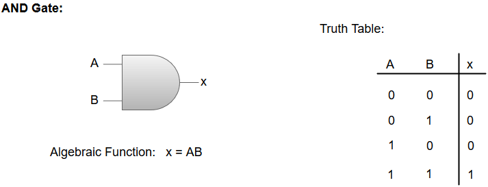
AND GATE:
The AND gate is an electronic circuit which gives a high output only if all its inputs are high. The AND operation is represented by a dot (.) sign.
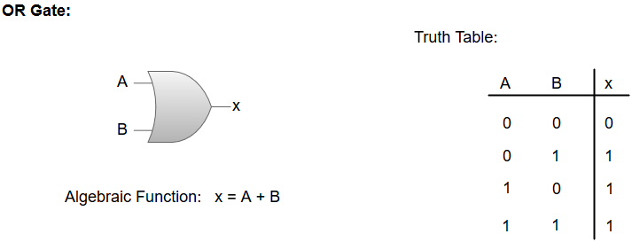
OR GATE:
The OR gate is an electronic circuit which gives a high output if one or more of its inputs are high. The operation performed by an OR gate is represented by a plus (+) sign.
NOT GATE:
The NOT gate is an electronic circuit which produces an inverted version of the input at its output. It is also known as an Inverter.
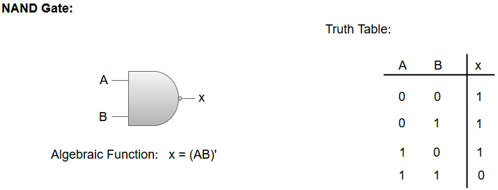
NAND GATE:
The NOT-AND (NAND) gate which is equal to an AND gate followed by a NOT gate. The NAND gate gives a high output if any of the inputs are low. The NAND gate is represented by a AND gate with a small circle on the output. The small circle represents inversion.
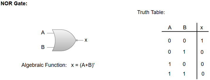
NOR GATE:
The NOT-OR (NOR) gate which is equal to an OR gate followed by a NOT gate. The NOR gate gives a low output if any of the inputs are high. The NOR gate is represented by an OR gate with a small circle on the output. The small circle represents inversion.
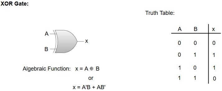
Exclusive-OR/ XOR GATE:
The 'Exclusive-OR' gate is a circuit which will give a high output if one of its inputs is high but not both of them. The XOR operation is represented by an encircled plus sign.
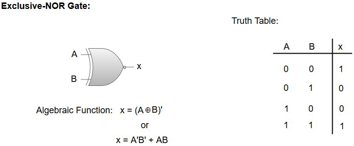
EXCLUSIVE-NOR/Equivalence GATE:
The 'Exclusive-NOR' gate is a circuit that does the inverse operation to the XOR gate. It will give a low output if one of its inputs is high but not both of them. The small circle represents inversion.