COA Tutorial
Basic CO and Design
Computer Instructions
Digital Logic Circuits
Map Simplification
Combinational Circuits
Flip - Flops
Digital Components
Register Transfer
Micro-Operations
Memory Organization
COA_Misc
- Booth's Multiplication Algorithm
- Branch Instruction in Computer Organization
- Data Representation in Computer Organization
- ALU and Data Path in Computer Organization
- External memory in Computer Organization
- Structured Computer Organization
- Types of Register in Computer Organization
- Secondary Storage Devices in Computer Organization
- Types of Operands in Computer Organization
- Serial Communication in Computer organization
- Addressing Sequencing in Computer Organization
- Simplified Instructional Computer (SIC)
- Arithmetic Instructions in AVR microcontroller
- Conventional Computing VS Quantum Computing
- Instruction set used in Simplified Instructional Computer
- Branch Instruction in AVR microcontroller
- Conditional Branch instruction in AVR Microcontroller
- Data transfer instruction in AVR microcontroller
- Difference between Memory-based and Register-based addressing modes
- Difference between 1's complement Representation and 2's complement Representation
- CALL Instructions and Stack in AVR Microcontroller
- Difference between Call and Jump Instructions
- Overflow in Arithmetic Addition in Binary number System
- Horizontal Micro-programmed Vs. Vertical Micro-programmed Control Unit
- Hardwired Vs. Micro-programmed Control Unit
- Non-Restoring Division Algorithm for Unsigned Integer
- Restoring Division Algorithm for Unsigned Integer
- Debugging a Machine-level Program
- Dependencies and Data Hazard in pipeline in Computer Organization
- Execution, Stages and Throughput in Pipeline
- Types of Pipeline Delay and Stalling
- Timing Diagram of MOV Instruction
- Advantages and Disadvantages of Flash Memory
- Importance/Need of negative feedback in amplifiers
- Anti-Aliasing - Computer Graphics
- Bus Arbitration in Computer Organization
- Convert a number from Base 2 (Binary) to Base 6
- Cache Coherence
- EHCI
- Cache Memory and Virtual Memory
- Electrical Potential and Potential Difference
- RAM and Cache
- SIM and RIM instructions in 8085 processor
- Clusters in Computer Organization
- Data Types and Addressing Modes of 80386/80386DX Microprocessor
Associative Memory
An associative memory can be considered as a memory unit whose stored data can be identified for access by the content of the data itself rather than by an address or memory location.
Associative memory is often referred to as Content Addressable Memory (CAM).
When a write operation is performed on associative memory, no address or memory location is given to the word. The memory itself is capable of finding an empty unused location to store the word.
On the other hand, when the word is to be read from an associative memory, the content of the word, or part of the word, is specified. The words which match the specified content are located by the memory and are marked for reading.
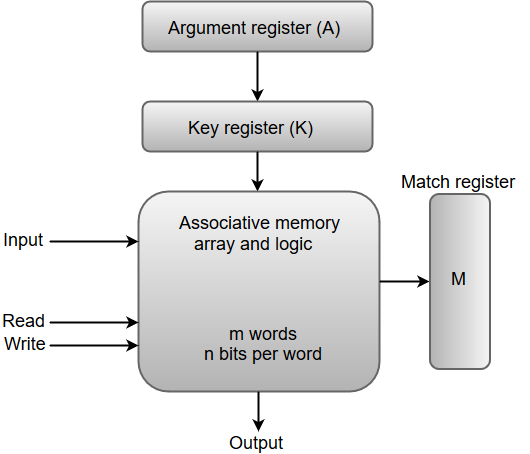
The following diagram shows the block representation of an Associative memory.

From the block diagram, we can say that an associative memory consists of a memory array and logic for 'm' words with 'n' bits per word.
The functional registers like the argument register A and key register K each have n bits, one for each bit of a word. The match register M consists of m bits, one for each memory word.
The words which are kept in the memory are compared in parallel with the content of the argument register.
The key register (K) provides a mask for choosing a particular field or key in the argument word. If the key register contains a binary value of all 1's, then the entire argument is compared with each memory word. Otherwise, only those bits in the argument that have 1's in their corresponding position of the key register are compared. Thus, the key provides a mask for identifying a piece of information which specifies how the reference to memory is made.
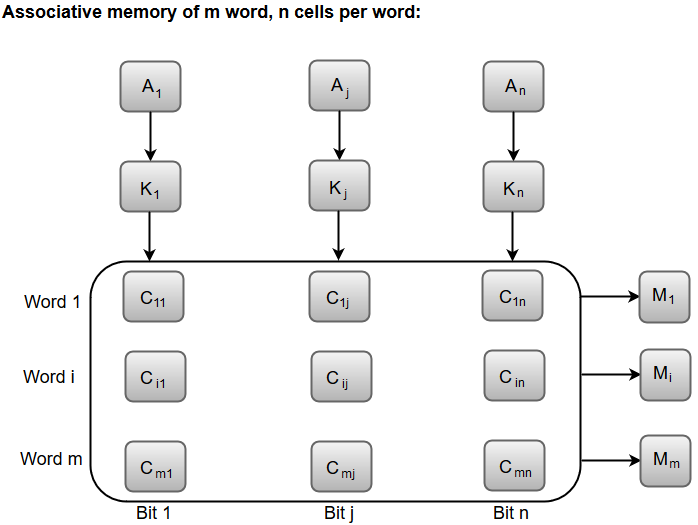
The following diagram can represent the relation between the memory array and the external registers in an associative memory.

The cells present inside the memory array are marked by the letter C with two subscripts. The first subscript gives the word number and the second specifies the bit position in the word. For instance, the cell Cij is the cell for bit j in word i.
A bit Aj in the argument register is compared with all the bits in column j of the array provided that Kj = 1. This process is done for all columns j = 1, 2, 3......, n.
If a match occurs between all the unmasked bits of the argument and the bits in word i, the corresponding bit Mi in the match register is set to 1. If one or more unmasked bits of the argument and the word do not match, Mi is cleared to 0.


