COA Tutorial
Basic CO and Design
Computer Instructions
Digital Logic Circuits
Map Simplification
Combinational Circuits
Flip - Flops
Digital Components
Register Transfer
Micro-Operations
Memory Organization
COA_Misc
- Booth's Multiplication Algorithm
- Branch Instruction in Computer Organization
- Data Representation in Computer Organization
- ALU and Data Path in Computer Organization
- External memory in Computer Organization
- Structured Computer Organization
- Types of Register in Computer Organization
- Secondary Storage Devices in Computer Organization
- Types of Operands in Computer Organization
- Serial Communication in Computer organization
- Addressing Sequencing in Computer Organization
- Simplified Instructional Computer (SIC)
- Arithmetic Instructions in AVR microcontroller
- Conventional Computing VS Quantum Computing
- Instruction set used in Simplified Instructional Computer
- Branch Instruction in AVR microcontroller
- Conditional Branch instruction in AVR Microcontroller
- Data transfer instruction in AVR microcontroller
- Difference between Memory-based and Register-based addressing modes
- Difference between 1's complement Representation and 2's complement Representation
- CALL Instructions and Stack in AVR Microcontroller
- Difference between Call and Jump Instructions
- Overflow in Arithmetic Addition in Binary number System
- Horizontal Micro-programmed Vs. Vertical Micro-programmed Control Unit
- Hardwired Vs. Micro-programmed Control Unit
- Non-Restoring Division Algorithm for Unsigned Integer
- Restoring Division Algorithm for Unsigned Integer
- Debugging a Machine-level Program
- Dependencies and Data Hazard in pipeline in Computer Organization
- Execution, Stages and Throughput in Pipeline
- Types of Pipeline Delay and Stalling
- Timing Diagram of MOV Instruction
- Advantages and Disadvantages of Flash Memory
- Importance/Need of negative feedback in amplifiers
- Anti-Aliasing - Computer Graphics
- Bus Arbitration in Computer Organization
- Convert a number from Base 2 (Binary) to Base 6
- Cache Coherence
- EHCI
- Cache Memory and Virtual Memory
- Electrical Potential and Potential Difference
- RAM and Cache
- SIM and RIM instructions in 8085 processor
- Clusters in Computer Organization
- Data Types and Addressing Modes of 80386/80386DX Microprocessor
Binary Adder-Subtractor
The Subtraction micro-operation can be done easily by taking the 2's compliment of addend bits and adding it to the augend bits.
Note: The 2's compliment can be obtained by taking the 1's compliment and adding one to the least significant pair of bits. The 1's compliment can be implemented with inverters, and one can be added to the sum through the input carry.
The Arithmetic micro-operations like addition and subtraction can be combined into one common circuit by including an exclusive-OR gate with each full adder.
The block diagram for a 4-bit adder-subtractor circuit can be represented as:
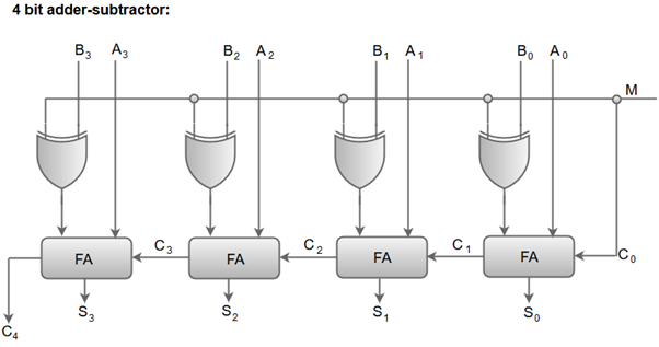
- When the mode input (M) is at a low logic, i.e. '0', the circuit act as an adder and when the mode input is at a high logic, i.e. '1', the circuit act as a subtractor.
- The exclusive-OR gate connected in series receives input M and one of the inputs B.
- When M is at a low logic, we have B⊕ 0 = B.
The full-adders receive the value of B, the input carry is 0, and the circuit performs A plus B. - When M is at a high logic, we have B⊕ 1 = B' and C0 = 1.
The B inputs are complemented, and a 1 is added through the input carry. The circuit performs the operation A plus the 2's complement of B.