COA Tutorial
Basic CO and Design
Computer Instructions
Digital Logic Circuits
Map Simplification
Combinational Circuits
Flip - Flops
Digital Components
Register Transfer
Micro-Operations
Memory Organization
COA_Misc
- Booth's Multiplication Algorithm
- Branch Instruction in Computer Organization
- Data Representation in Computer Organization
- ALU and Data Path in Computer Organization
- External memory in Computer Organization
- Structured Computer Organization
- Types of Register in Computer Organization
- Secondary Storage Devices in Computer Organization
- Types of Operands in Computer Organization
- Serial Communication in Computer organization
- Addressing Sequencing in Computer Organization
- Simplified Instructional Computer (SIC)
- Arithmetic Instructions in AVR microcontroller
- Conventional Computing VS Quantum Computing
- Instruction set used in Simplified Instructional Computer
- Branch Instruction in AVR microcontroller
- Conditional Branch instruction in AVR Microcontroller
- Data transfer instruction in AVR microcontroller
- Difference between Memory-based and Register-based addressing modes
- Difference between 1's complement Representation and 2's complement Representation
- CALL Instructions and Stack in AVR Microcontroller
- Difference between Call and Jump Instructions
- Overflow in Arithmetic Addition in Binary number System
- Horizontal Micro-programmed Vs. Vertical Micro-programmed Control Unit
- Hardwired Vs. Micro-programmed Control Unit
- Non-Restoring Division Algorithm for Unsigned Integer
- Restoring Division Algorithm for Unsigned Integer
- Debugging a Machine-level Program
- Dependencies and Data Hazard in pipeline in Computer Organization
- Execution, Stages and Throughput in Pipeline
- Types of Pipeline Delay and Stalling
- Timing Diagram of MOV Instruction
- Advantages and Disadvantages of Flash Memory
- Importance/Need of negative feedback in amplifiers
- Anti-Aliasing - Computer Graphics
- Bus Arbitration in Computer Organization
- Convert a number from Base 2 (Binary) to Base 6
- Cache Coherence
- EHCI
- Cache Memory and Virtual Memory
- Electrical Potential and Potential Difference
- RAM and Cache
- SIM and RIM instructions in 8085 processor
- Clusters in Computer Organization
- Data Types and Addressing Modes of 80386/80386DX Microprocessor
Booth's Multiplication Algorithm
The booth algorithm is a multiplication algorithm that allows us to multiply the two signed binary integers in 2's complement, respectively. It is also used to speed up the performance of the multiplication process. It is very efficient too. It works on the string bits 0's in the multiplier that requires no additional bit only shift the right-most string bits and a string of 1's in a multiplier bit weight 2k to weight 2m that can be considered as 2k+ 1 - 2m.
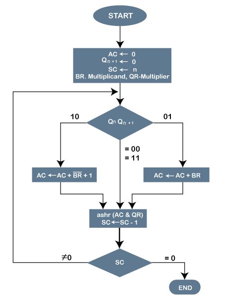
Following is the pictorial representation of the Booth's Algorithm:

In the above flowchart, initially, AC and Qn + 1 bits are set to 0, and the SC is a sequence counter that represents the total bits set n, which is equal to the number of bits in the multiplier. There are BR that represent the multiplicand bits, and QR represents the multiplier bits. After that, we encountered two bits of the multiplier as Qn and Qn + 1, where Qn represents the last bit of QR, and Qn + 1 represents the incremented bit of Qn by 1. Suppose two bits of the multiplier is equal to 10; it means that we have to subtract the multiplier from the partial product in the accumulator AC and then perform the arithmetic shift operation (ashr). If the two of the multipliers equal to 01, it means we need to perform the addition of the multiplicand to the partial product in accumulator AC and then perform the arithmetic shift operation (ashr), including Qn + 1. The arithmetic shift operation is used in Booth's algorithm to shift AC and QR bits to the right by one and remains the sign bit in AC unchanged. And the sequence counter is continuously decremented till the computational loop is repeated, equal to the number of bits (n).
Working on the Booth Algorithm
- Set the Multiplicand and Multiplier binary bits as M and Q, respectively.
- Initially, we set the AC and Qn + 1 registers value to 0.
- SC represents the number of Multiplier bits (Q), and it is a sequence counter that is continuously decremented till equal to the number of bits (n) or reached to 0.
- A Qn represents the last bit of the Q, and the Qn+1 shows the incremented bit of Qn by 1.
- On each cycle of the booth algorithm, Qn and Qn + 1 bits will be checked on the following parameters as follows:
- When two bits Qn and Qn + 1 are 00 or 11, we simply perform the arithmetic shift right operation (ashr) to the partial product AC. And the bits of Qn and Qn + 1 is incremented by 1 bit.
- If the bits of Qn and Qn + 1 is shows to 01, the multiplicand bits (M) will be added to the AC (Accumulator register). After that, we perform the right shift operation to the AC and QR bits by 1.
- If the bits of Qn and Qn + 1 is shows to 10, the multiplicand bits (M) will be subtracted from the AC (Accumulator register). After that, we perform the right shift operation to the AC and QR bits by 1.
- The operation continuously works till we reached n - 1 bit in the booth algorithm.
- Results of the Multiplication binary bits will be stored in the AC and QR registers.
There are two methods used in Booth's Algorithm:
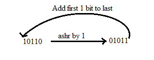
1. RSC (Right Shift Circular)
It shifts the right-most bit of the binary number, and then it is added to the beginning of the binary bits.

2. RSA (Right Shift Arithmetic)
It adds the two binary bits and then shift the result to the right by 1-bit position.
Example: 0100 + 0110 => 1010, after adding the binary number shift each bit by 1 to the right and put the first bit of resultant to the beginning of the new bit.
Example: Multiply the two numbers 7 and 3 by using the Booth's multiplication algorithm.
Ans. Here we have two numbers, 7 and 3. First of all, we need to convert 7 and 3 into binary numbers like 7 = (0111) and 3 = (0011). Now set 7 (in binary 0111) as multiplicand (M) and 3 (in binary 0011) as a multiplier (Q). And SC (Sequence Count) represents the number of bits, and here we have 4 bits, so set the SC = 4. Also, it shows the number of iteration cycles of the booth's algorithms and then cycles run SC = SC - 1 time.
| Qn | Qn + 1 | M = (0111) M' + 1 = (1001) & Operation |
AC | Q | Qn + 1 | SC |
|---|---|---|---|---|---|---|
| 1 | 0 | Initial | 0000 | 0011 | 0 | 4 |
| Subtract (M' + 1) | 1001 | |||||
| 1001 | ||||||
| Perform Arithmetic Right Shift operations (ashr) | 1100 | 1001 | 1 | 3 | ||
| 1 | 1 | Perform Arithmetic Right Shift operations (ashr) | 1110 | 0100 | 1 | 2 |
| 0 | 1 | Addition (A + M) | 0111 | |||
| 0101 | 0100 | |||||
| Perform Arithmetic right shift operation | 0010 | 1010 | 0 | 1 | ||
| 0 | 0 | Perform Arithmetic right shift operation | 0001 | 0101 | 0 | 0 |
The numerical example of the Booth's Multiplication Algorithm is 7 x 3 = 21 and the binary representation of 21 is 10101. Here, we get the resultant in binary 00010101. Now we convert it into decimal, as (000010101)10 = 2*4 + 2*3 + 2*2 + 2*1 + 2*0 => 21.
Example: Multiply the two numbers 23 and -9 by using the Booth's multiplication algorithm.
Here, M = 23 = (010111) and Q = -9 = (110111)
| Qn Qn + 1 | M = 0 1 0 1 1 1 M' + 1 = 1 0 1 0 0 1 |
AC | Q | Qn + 1 SC |
|---|---|---|---|---|
| Initially | 000000 | 110111 | 0 6 | |
| 1 0 | Subtract M | 101001 | ||
| 101001 | ||||
| Perform Arithmetic right shift operation | 110100 | 111011 | 1 5 | |
| 1 1 | Perform Arithmetic right shift operation | 111010 | 011101 | 1 4 |
| 1 1 | Perform Arithmetic right shift operation | 111101 | 001110 | 1 3 |
| 0 1 | Addition (A + M) | 010111 | ||
| 010100 | ||||
| Perform Arithmetic right shift operation | 001010 | 000111 | 0 2 | |
| 1 0 | Subtract M | 101001 | ||
| 110011 | ||||
| Perform Arithmetic right shift operation | 111001 | 100011 | 1 1 | |
| 1 1 | Perform Arithmetic right shift operation | 111100 | 110001 | 1 0 |
Qn + 1 = 1, it means the output is negative.
Hence, 23 * -9 = 2's complement of 111100110001 => (00001100111)


