COA Tutorial
Basic CO and Design
Computer Instructions
Digital Logic Circuits
Map Simplification
Combinational Circuits
Flip - Flops
Digital Components
Register Transfer
Micro-Operations
Memory Organization
COA_Misc
- Booth's Multiplication Algorithm
- Branch Instruction in Computer Organization
- Data Representation in Computer Organization
- ALU and Data Path in Computer Organization
- External memory in Computer Organization
- Structured Computer Organization
- Types of Register in Computer Organization
- Secondary Storage Devices in Computer Organization
- Types of Operands in Computer Organization
- Serial Communication in Computer organization
- Addressing Sequencing in Computer Organization
- Simplified Instructional Computer (SIC)
- Arithmetic Instructions in AVR microcontroller
- Conventional Computing VS Quantum Computing
- Instruction set used in Simplified Instructional Computer
- Branch Instruction in AVR microcontroller
- Conditional Branch instruction in AVR Microcontroller
- Data transfer instruction in AVR microcontroller
- Difference between Memory-based and Register-based addressing modes
- Difference between 1's complement Representation and 2's complement Representation
- CALL Instructions and Stack in AVR Microcontroller
- Difference between Call and Jump Instructions
- Overflow in Arithmetic Addition in Binary number System
- Horizontal Micro-programmed Vs. Vertical Micro-programmed Control Unit
- Hardwired Vs. Micro-programmed Control Unit
- Non-Restoring Division Algorithm for Unsigned Integer
- Restoring Division Algorithm for Unsigned Integer
- Debugging a Machine-level Program
- Dependencies and Data Hazard in pipeline in Computer Organization
- Execution, Stages and Throughput in Pipeline
- Types of Pipeline Delay and Stalling
- Timing Diagram of MOV Instruction
- Advantages and Disadvantages of Flash Memory
- Importance/Need of negative feedback in amplifiers
- Anti-Aliasing - Computer Graphics
- Bus Arbitration in Computer Organization
- Convert a number from Base 2 (Binary) to Base 6
- Cache Coherence
- EHCI
- Cache Memory and Virtual Memory
- Electrical Potential and Potential Difference
- RAM and Cache
- SIM and RIM instructions in 8085 processor
- Clusters in Computer Organization
- Data Types and Addressing Modes of 80386/80386DX Microprocessor
EHCI

EHCI stands for Enhanced Host Controller Interface and is responsible for defining the register-level interface of the host controller of USB 2.0. it specifies both the hardware and software interface between the software of your system and the controller hardware.
It acts as a bridge between the hardware of the controller and the system software. The specification is defined for the system builders and system driver developers.
To understand the specification, the reader should know about USB 2.0 Specifications. There are certain conflicts between the provided version specification and the USB 2. specifications. But in case of any conflicts, precedence is given to the USB 2.0 specification.
Hello Java Program for Beginners
The reader must be familiar with the Universal Serial Bus Specification, Revision 2.0. Despite due diligence, there may exist conflicts between this specification and the USB 2.0 Specification.
USB 2.0 Host Controller
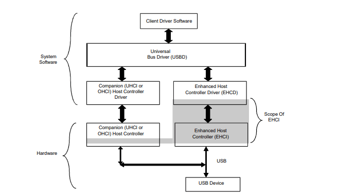
The companion host controller can be any USB 1.1 host controller. It can either be OHCI or UHC. The companion host controller handles both full and low-speed USB devices. These devices should be connected to the root ports of the system. The cHCs don't know about the working of the high-speed mode host controller.
The high-speed devices are maintained and managed by the EHCI host controller. They can be included in a USB 2.0 host controller without changing. When the eHC was executed and configured, the host controller was assigned as the owner of all the root ports in the system.
The eHC and the drivers of the host controllers find all the attached devices. It also includes extra control bits that can be seen in each port register that handles the routing logic.
As discussed, the drivers' ownership is primarily given to the eHC. When the device is not a high-speed device, the eHC drivers release the ownership of this device. The control of the device is released, and ownership is assigned to a companion host controller.
For the particular port, enumeration begins from the initial point of attachment. The device connected to this point is enumerated under the companion host controller. Otherwise, eHC retains the port ownership. Then the enumeration is done under the eHC. The USB 2.0 specifications do not provide descriptions for both UHCI and OHCI. It defines the register and schedule interface to the EHCI.
The key features provided by the Enhanced Host Controller Interface are as follows:
- Complete, Robust Support for all USB 2.0 Features: The hardware and software specifications defined by the EHCI provide the user with a host controller that completes all the requirements of USB2.0 low, high and full-speed devices. This even includes the support for the latest feature provided by USB2.0, such as split transactions and additional extensions to some protocols, such as the new PING protocol.
- Low-risk support: It also provides risk support for both full and low-speed peripherals. It supports all three device speeds that are high, low, and full on the root ports. This is achieved by integrating the current hardware and software for USB1.1 host controllers to support both full and low devices connected to those ports. This enables the host controller interface to provide more efficient support to high-speed devices without trading off the complexity of the full or low-speed devices.
- Power Management: The present computer architecture supports aggressive power management in the system. The host controller must implement a PCI power management interface if the implementation requires PCI configuration registers. USB devices are essential for providing a consistent and robust user experience.
- Resolves issues associated with USB 1.1 Host Controller: It provided easier and more robust solutions to the problems faced by the user when using the USB 1.1 Host Controller Issues. The EHCI specifications provide solutions to problematic issues for the controllers. Some of the issues resolved in EHCI specifications included memory thrashing, power management conflicts, and issues regarding memory access efficiency. The new architecture introduced in the EHCI added new features and solved the issues with the previous versions.
- Optimized memory access: The EHCI was developed to implement a method that enabled the controller to reduce the average number of memory access needed to implement a USB transaction. Each data structure in the schedule is optimized to define the data buffers for large clients. This reduces the memory footprint and the amount of overhead to travel through the schedule.
- Reduced Hardware Complexity: The Enhanced Host Controller Interface provided a simpler, asynchronous interface than the previous host controller interfaces for the software. This provided the controller with parameterized work items. The controller uses these items to implement the transactions in the USB. The interface enables the software to add new tasks to the interface asynchronously. The host controller executes the operation without needing any synchronization. The interface provided support for a simple hardware scatter-gather method that could be implemented for all the data structures in the interface.
- Support for both 32 and 64-bit Addressing: the developers of Enhanced Host Controller Interface visioned that during the implementation of the EHCI, there may be a possibility that the interface will be used in certain architectures that provide support for 64-bit addressable memory space. So, the developers included an additional interface extension that enabled the user to implement the interface to provide support for 64-bit addressing.
General Architecture of Enhanced Host Controller Interface

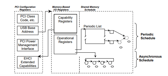
The schedule interface in EHCI has separate schedules for each category of transfer type mentioned above. The EHCI provides support for both asynchronous transfer and periodic transfer. The periodic transfer supported by the EHCI includes both isochronous and interrupt, while the asynchronous transfer supported by EHCI includes control and bulk type transfer.
The periodic schedule is a time-based frame list that resembles a sliding window of time of the controller items. Both types of periodic transfer that is, isochronous and interrupt transfers, are facilitated by the periodic schedule. The asynchronous schedule is a circular list of work items that implements round-robin service to all the asynchronous transfers.
The software can also start or stop any schedule using the EHCI. This allows the software to keep the USB alive with SOF traffic. When the EHCI disables both schedules, the controller won't be able to access the scheduled space. Thus, the host controller cannot access the main memory with both schedules disabled. This allows mobile systems the better utilization of CPU power.
The internal architecture of EHCI
The Enhanced Host Controller Interface defines three spaces of the interface:
- PCI Configuration Space: if the execution requires the use of PCI registers. The registers are responsible for system component enumeration and PCI power management.
- Register Space: This provides space for implementing specific parameters, capabilities, and status registers. The implementation should be used as memory-mapped I/O space. The register space is also referred to as the I/O space.
- Scheduled Interface Space: This is the memory provided and controlled by the Enhanced Host Control Driver. It is used for periodic and asynchronous schedules.
EHCI Schedule Data Structures
The Enhanced Host Controller Interface handles and controls the interrupt, bulk, and control transfer types. It uses a simple buffer to queue the data structure.
It uses the queue data structure to facilitate automatic, in-order data transfer streaming. It enables the software to add the data buffers asynchronously to the queue, which maintains continuous streaming. USB-defined short packet semantics are supported on all the processing boundary conditions. This does not require any additional intervention from the software.
The split transaction is used for both full and low-speed non-isochronous transfers. The split transactions are handled as a simple extension of the high-speed model. The same data structures also handle them. User interface data structures control the full and high-speed isochronous transfers.
Root Hub Emulation
A host controller must use a port hub. The operational register space has the port registers that include the minimum hardware status and control required to handle each port register within the USB specification.
The host controller moves through the EHCI schedules and encounters the work items. This results in the host controllers implementing the USB transactions.
The transactions are shared with all the root ports enabled and connected to downstream USB devices. The port register provides the control and status report needed to manipulate the port with respect to the USB specification.


