Computer Graphics
Graphic Systems
Input-Output Devices
Scan Conversion a line
Scan Conversion Circle
Scan Converting Ellipse
Filled Area Primitives
2D Transformations
2D-Viewing
Clipping Techniques
Pointing & Positioning
3D Computer Graphics
Hidden Surfaces
Projection
Programs
Weiler-Atherton Polygon Clipping
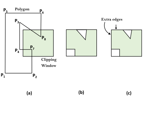
When the clipped polygons have two or more separate sections, then it is the concave polygon handled by this algorithm. The vertex-processing procedures for window boundaries are modified so that concave polygon is displayed.
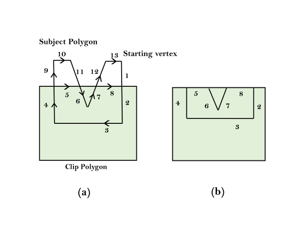
Let the clipping window be initially called clip polygon and the polygon to be clipped the subject polygon. We start with an arbitrary vertex of the subject polygon and trace around its border in the clockwise direction until an intersection with the clip polygon is encountered:
1. If the edge enters the clip polygon, record the intersection point and continue to trace the subject polygon.

2. If the edge leaves the clip polygon, record the intersection point and make a right turn to follow the clip polygon in the same manner (i.e., treat the clip polygon as subject polygon and the subject polygon as clip polygon and proceed as before).
Whenever our path of traversal forms a sub-polygon we output the sub-polygon as part of the overall result. We then continue to trace the rest of the original subject polygon from a recorded intersection point that marks the beginning of a not-yet traced edge or portion of an edge. The algorithm terminates when the entire border of the original subject polygon has been traced exactly once.

For example, the number in fig (a) indicates the order in which the edges and portion of edges are traced. We begin at the starting vertex and continue along the same edge (from 1 to 2) of the subject polygon as it enters the clip polygon. As we move along the edge that is leaving the clip polygon, we make a right turn (from 4 to 5) onto the clip polygon, which is now considered the subject polygon. Following the same logic leads to the next right turn (from 5 to 6) onto the current clip polygon, this is the original subject polygon. With the next step done (from 7 to 8) in the same way, we have a sub-polygon for output in fig (b). We then resume our traversal of the original subject polygon from the recorded intersection point where we first changed our course. Going from 9 to 10 to 11 produces no output. After skipping the already traversed 6 and 7, we continue with 12 and 13 and come to an end. The fig (b) is the final result.


