Computer Graphics
Graphic Systems
Input-Output Devices
Scan Conversion a line
Scan Conversion Circle
Scan Converting Ellipse
Filled Area Primitives
2D Transformations
2D-Viewing
Clipping Techniques
Pointing & Positioning
3D Computer Graphics
Hidden Surfaces
Projection
Programs
Parallel Projection
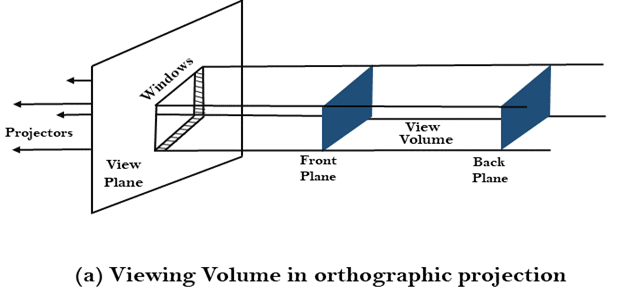
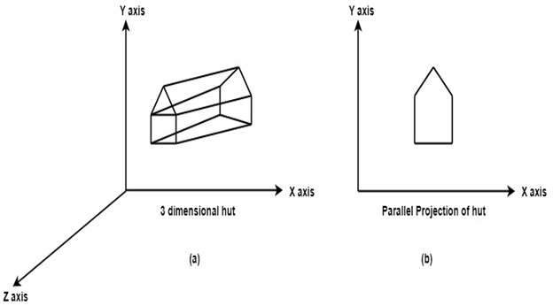
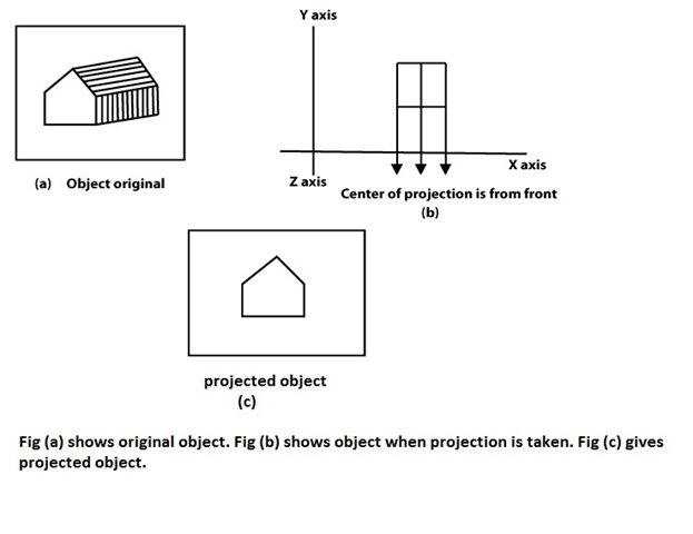
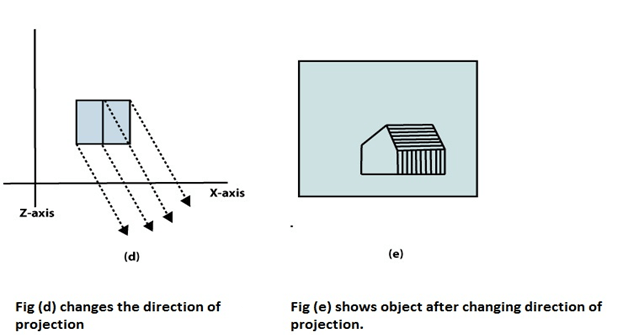
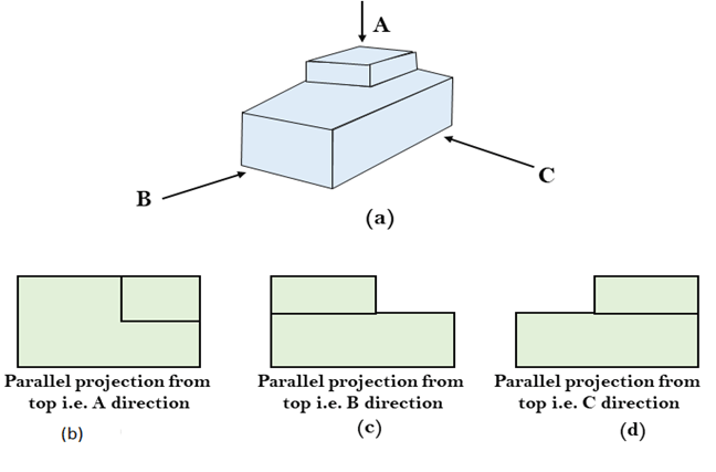
Parallel Projection use to display picture in its true shape and size. When projectors are perpendicular to view plane then is called orthographic projection. The parallel projection is formed by extending parallel lines from each vertex on the object until they intersect the plane of the screen. The point of intersection is the projection of vertex.
Parallel projections are used by architects and engineers for creating working drawing of the object, for complete representations require two or more views of an object using different planes.
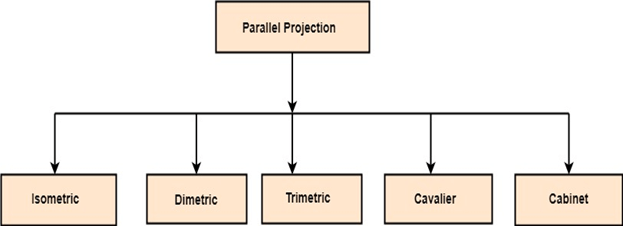
- Isometric Projection: All projectors make equal angles generally angle is of 30°.
- Dimetric: In these two projectors have equal angles. With respect to two principle axis.
- Trimetric: The direction of projection makes unequal angle with their principle axis.
- Cavalier: All lines perpendicular to the projection plane are projected with no change in length.
- Cabinet: All lines perpendicular to the projection plane are projected to one half of their length. These give a realistic appearance of object.
